Roboforming is a dieless Incremental Forming Process utilizing 2 synchronized Robots. Each robot is equipt with a sphere-tipped tool-head known as a dapper-punch. The ‘master’ robot is supported by the ‘slave’ robot. A sheet of metal or plastic is secured between the two robots in a sturdy frame. The master robot pushes incrementally (millimeter by millimeter) on the sheet, forming the sheet in the shape of the tool-path, The slave robot provides leverage on the opposite side of the sheet for the master robot to push against. Roboforming, also known as ‘Robot Assisted Asymmetric Incremental Sheet Forming.’ (Bruninghaus) actaully refers to two processes known as Roboforming Refers to DPIF-P and DPIF-L. DPIF is a variant of Asymmetric Incremental Sheet Forming (AISF), which has been developing since the early 1990s. (Bruninghaus, 1)
Types of Roboforming
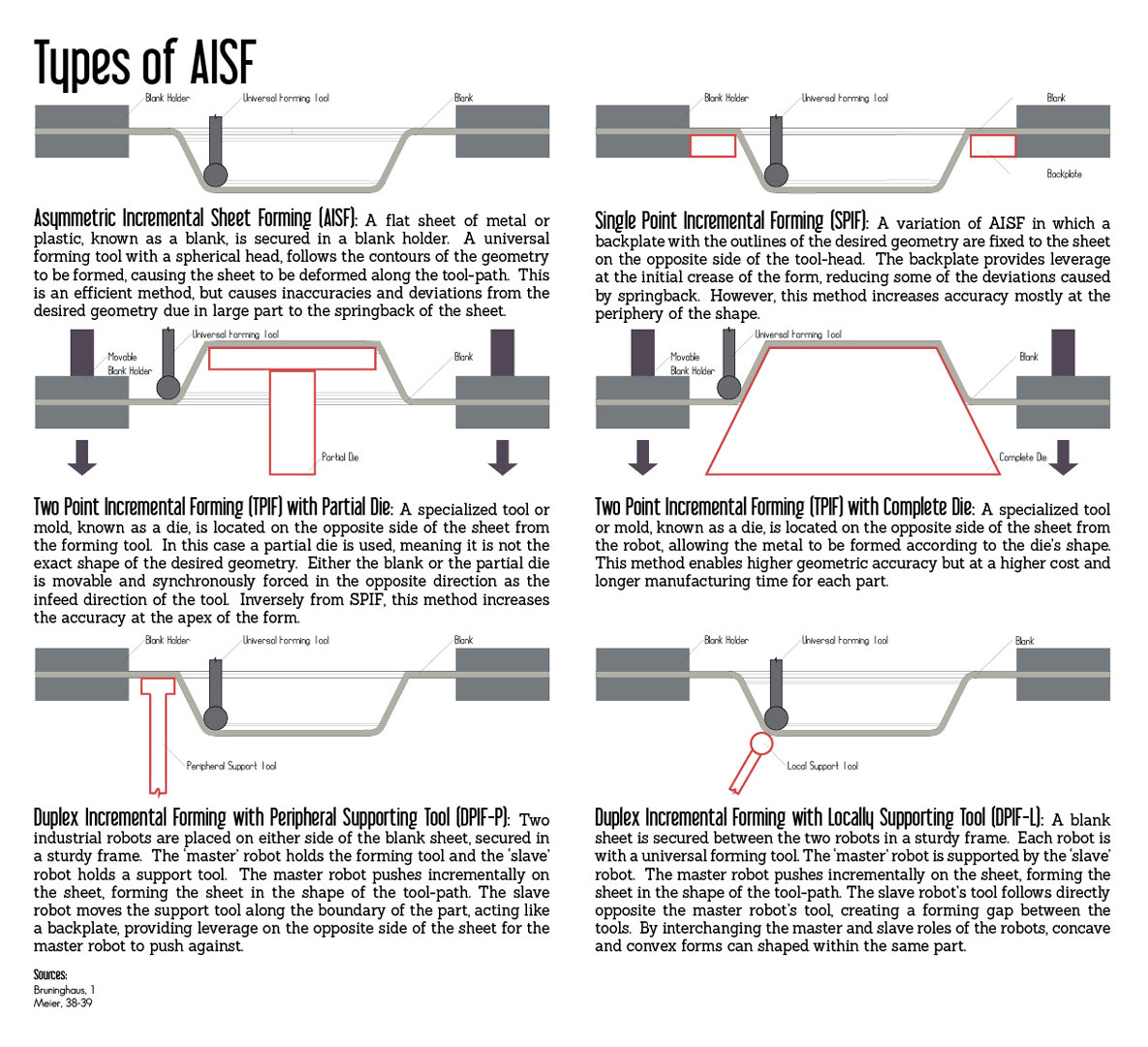
Asymmetric Incremental Sheet Forming (AISF): A flat sheet of metal or plastic, known as a blank, is secured in a blank holder. A universal forming tool with a spherical head, follows the contours of the geometry to be formed, causing the sheet to be deformed along the tool-path. This is an efficient method, but causes inaccuracies and deviations from the desired geometry due in large part to the springback of the sheet.
Single Point Incremental Forming (SPIF): A variation of AISF in which a backplate with the outlines of the desired geometry are fixed to the sheet on the opposite side of the tool-head. The backplate provides leverage at the initial crease of the form, reducing some of the deviations caused by springback. However, this method increases accuracy mostly at the periphery of the shape.
Two Point Incremental Forming (TPIF) with Partial Die: A specialized tool or mold, known as a die, is located on the opposite side of the sheet from the forming tool. In this case a partial die is used, meaning it is not the exact shape of the desired geometry. Either the blank or the partial die is movable and synchronously forced in the opposite direction as the infeed direction of the tool. Inversely from SPIF, this method increases the accuracy at the apex of the form.
Two Point Incremental Forming (TPIF) with Complete Die: A specialized tool or mold, known as a die, is located on the opposite side of the sheet from the robot, allowing the metal to be formed according to the die’s shape. This method enables higher geometric accuracy but at a higher cost and longer manufacturing time for each part.
Duplex Incremental Forming with Peripheral Supporting Tool (DPIF-P): Two industrial robots are placed on either side of the blank sheet, secured in a sturdy frame. The ‘master’ robot holds the forming tool and the ‘slave’ robot holds a support tool. The master robot pushes incrementally on the sheet, forming the sheet in the shape of the tool-path. The slave robot moves the support tool along the boundary of the part, acting like a backplate, providing leverage on the opposite side of the sheet for the master robot to push against.
Duplex Incremental Forming with Locally Supporting Tool (DPIF-L): A blank sheet is secured between the two robots in a sturdy frame. Each robot is equipt with a universal forming tool. The ‘master’ robot is supported by the ‘slave’ robot. The master robot pushes incrementally on the sheet, forming the sheet in the shape of the tool-path. The slave robot’s tool follows directly opposite the master robot’s tool, creating a forming gap between the tools. By interchanging the master and slave roles of the the robots, concave and convex forms can shaped within the same part.
Tool Path Options
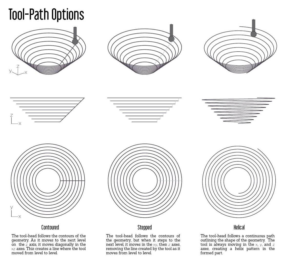
Contoured: The tool-head follows the contours of the geometry. As it moves to the next level on the z axis, it moves diagonally in the xz axes. This creates a line where the tool moved from level to level.
Stepped: The tool-head follows the contours of the geometry, but when it steps to the next level, it moves in the xy, then z axes, removing the line created by the tool as it moves from level to level.
Helical: The tool-head follows a continuous path outlining the shape of the geometry. The tool is always moving in the x, y, and z axes, creating a helix pattern in the formed part.
Tool Options
Universal Forming Tools
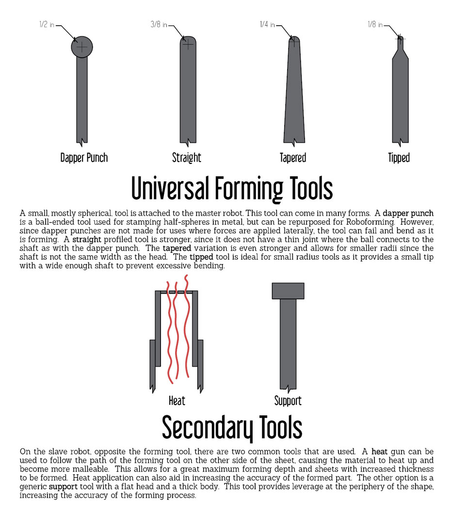
A small, mostly spherical, tool is attached to the master robot. This tool can come in many forms. A dapper punch is a ball-ended tool used for stamping half-spheres in metal, but can be repurposed for Roboforming. However, since dapper punches are not made for uses where forces are applied laterally, the tool can fail and bend as it is forming. A straight profiled tool is stronger, since it does not have a thin joint where the ball connects to the shaft as with the dapper punch. The tapered variation is even stronger and allows for smaller radii since the shaft is not the same width as the head. The tipped tool is ideal for small radius tools as it provides a small tip with a wide enough shaft to prevent excessive bending.
Supporting Tools
On the slave robot, opposite the forming tool, there are two common tools that are used. A heat gun can be used to follow the path of the forming tool on the other side of the sheet, causing the material to heat up and become more malleable. This allows for a great maximum forming depth and sheets with increased thickness to be formed. Heat application can also aid in increasing the accuracy of the formed part. The other option is a generic support tool with a flat head and a thick body. This tool provides leverage at the periphery of the shape, increasing the accuracy of the forming process.
Roboforming is Scalable
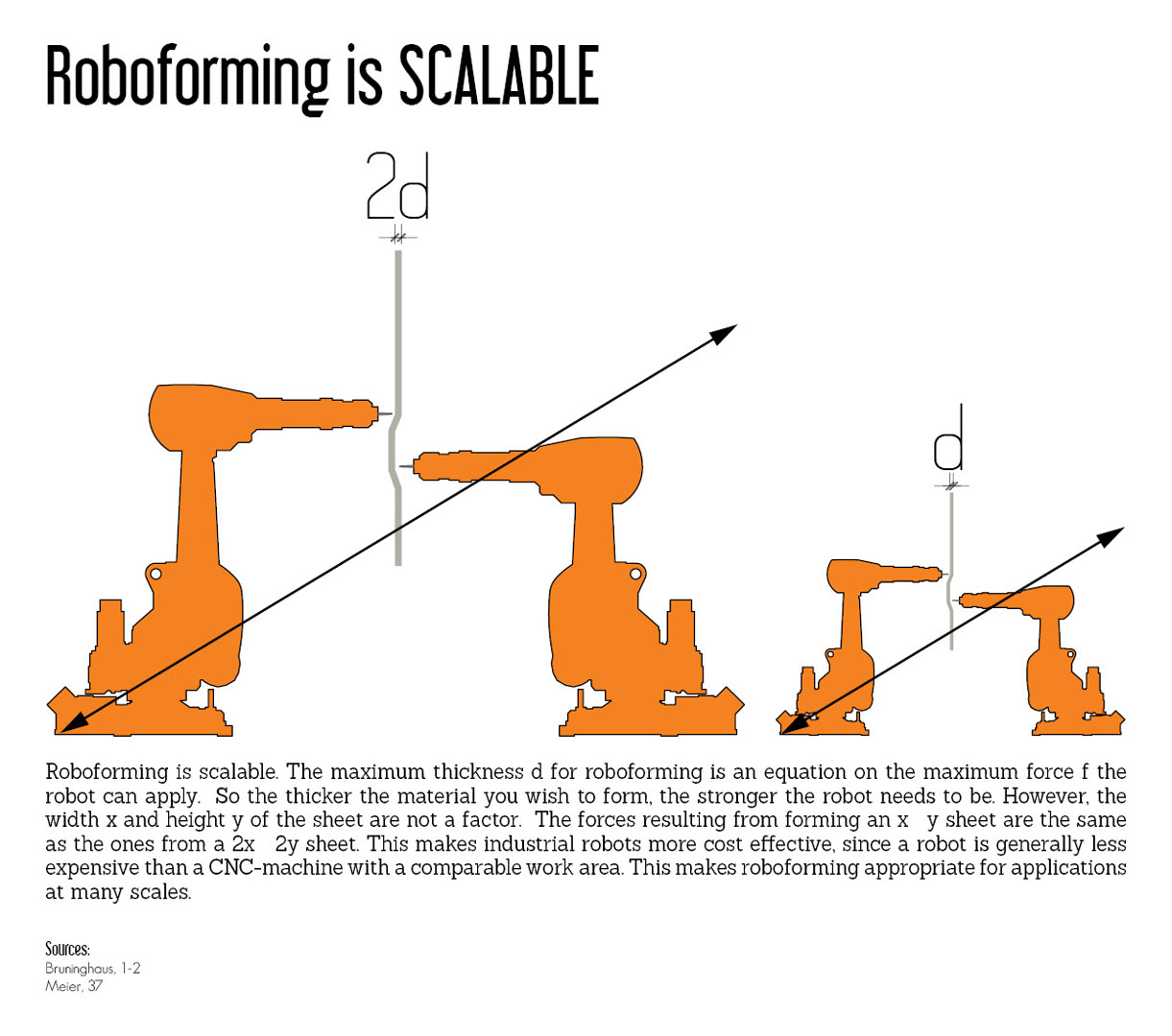
Roboforming is scalable. The maximum thickness d for roboforming is an equation on the maximum force f the robot can apply. So the thicker the material you wish to form, the stronger the robot needs to be. However, the width x and height y of the sheet are not a factor. The forces resulting from forming an x y sheet are the same as the ones from a 2x 2y sheet. This makes industrial robots more cost effective, since a robot is generally less expensive than a CNC-machine with a comparable work area. This makes roboforming appropriate for applications at many scales.
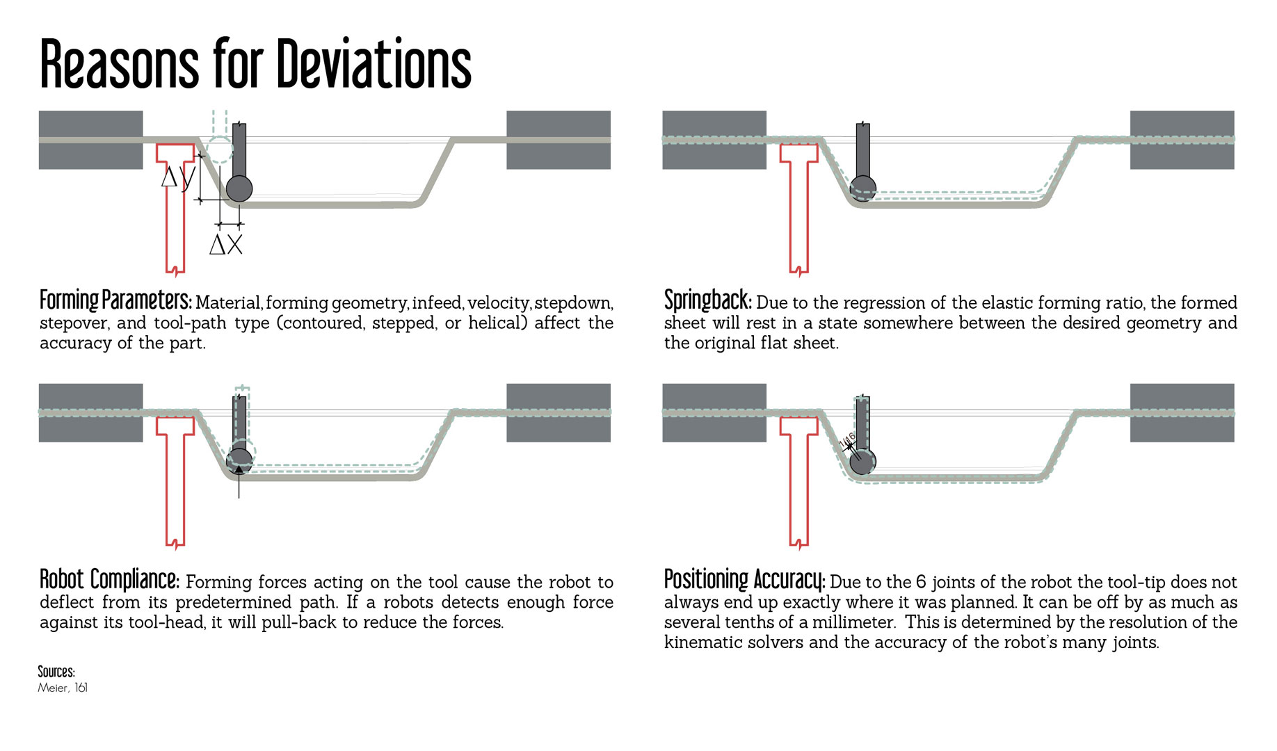
Reasons for Deviations
Forming Parameters: Material, forming geometry, infeed, velocity, stepdown, stepover, and tool-path type (contoured, stepped, or helical) affect the accuracy of the part.
Springback: Due to the regression of the elastic forming ratio, the formed sheet will rest in a state somewhere between the desired geometry and the original flat sheet.
Robot Compliance: Forming forces acting on the tool cause the robot to deflect from its predetermined path. If a robots detects enough force against its tool-head, it will pull-back to reduce the forces.
Positioning Accuracy: Due to the 6 joints of the robot the tool-tip does not always end up exactly where it was planned. It can be off by as much as several tenths of a millimeter. This is determined by the resolution of the kinematic solvers and the accuracy of the robot’s many joints.
Leave a Reply